
Wire Paths
The default path is an orthogonal polyline generated by the program. When you need to route around a component, press against the frame, or follow a duct, intervene manually with 控制点 (control points): only the points you drag are treated as fixed requirements; the auto-generated bends can be rearranged at any time.
What the Handles Are
With the 选择 (Select) tool, click a wire and three kinds of draggable markers appear on it:
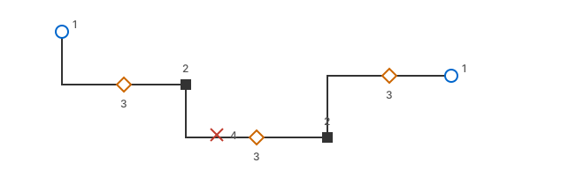
Behavior While Dragging
- All drop positions follow the page's Snap to Grid setting and the 6 mm endpoint snap.
- The program knows each point's travel direction: dragging a midpoint off a straight segment keeps it aligned with both ends (it will not turn into a Z), and dragging a corner keeps the orientation of its two segments. So "one nudge turns the whole wire into a zigzag" cannot happen.
- Only the point being dragged and manual control points take part in the constraints; auto-generated bends are not locked and get replaced when the wire is rerouted.
- One continuous drag registers as a single undo step; networks, wire-number labels, check markers, and label layout are recomputed only after you release — so dragging stays very light and the page is never redrawn pixel by pixel.
- When a component moves or rotates, the wire endpoints attached to it follow; existing manual control points keep their positions and the path is automatically patched between them.
Back to Auto Routing
The 导线属性 ▸ 路径 (Wire Properties ▸ Path) section shows 拐点 N 个 (N bends) and, when manual points exist, appends the blue 手动控制点 N 个 (N manual control points); manual points are marked with ● in the point list. To hand everything back to the program:
- Click the 恢复自动布线 (Restore Auto Routing) button, or choose the same-named item from the wire's context menu. With several wires selected, use 排列 ▸ 恢复自动布线 (Arrange ▸ Restore Auto Routing, ⇧⌘K) to clear all manual points in one batch and one undo step.
- When there are no manual control points the button/menu item is unavailable (the wire is already fully automatic).
- To change just one point: double-click that solid control point.
Tip
The path does not affect electrical relationships. Editing the path only changes how the wire looks on the sheet; it does not change connections: endpoint bindings, junctions, networks, and numbering-rule decisions are all independent of where the bends sit. What actually breaks a connection is dragging an endpoint away from a pin/junction (making it dangling), or dragging a wire off another wire.
Crossings and Junctions
Manual routing often ends up crossing another line. Remember: a crossing is not a connection. To connect, use the toolbar's 接点 (Junction) tool and click on the crossing; to keep them separate, simply leave the plain cross — both cases are explained in Wiring.